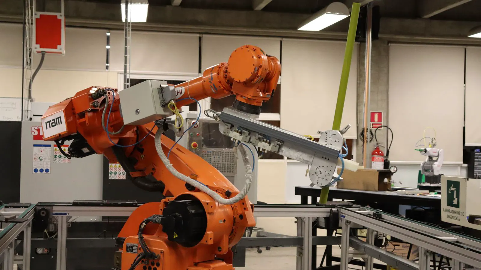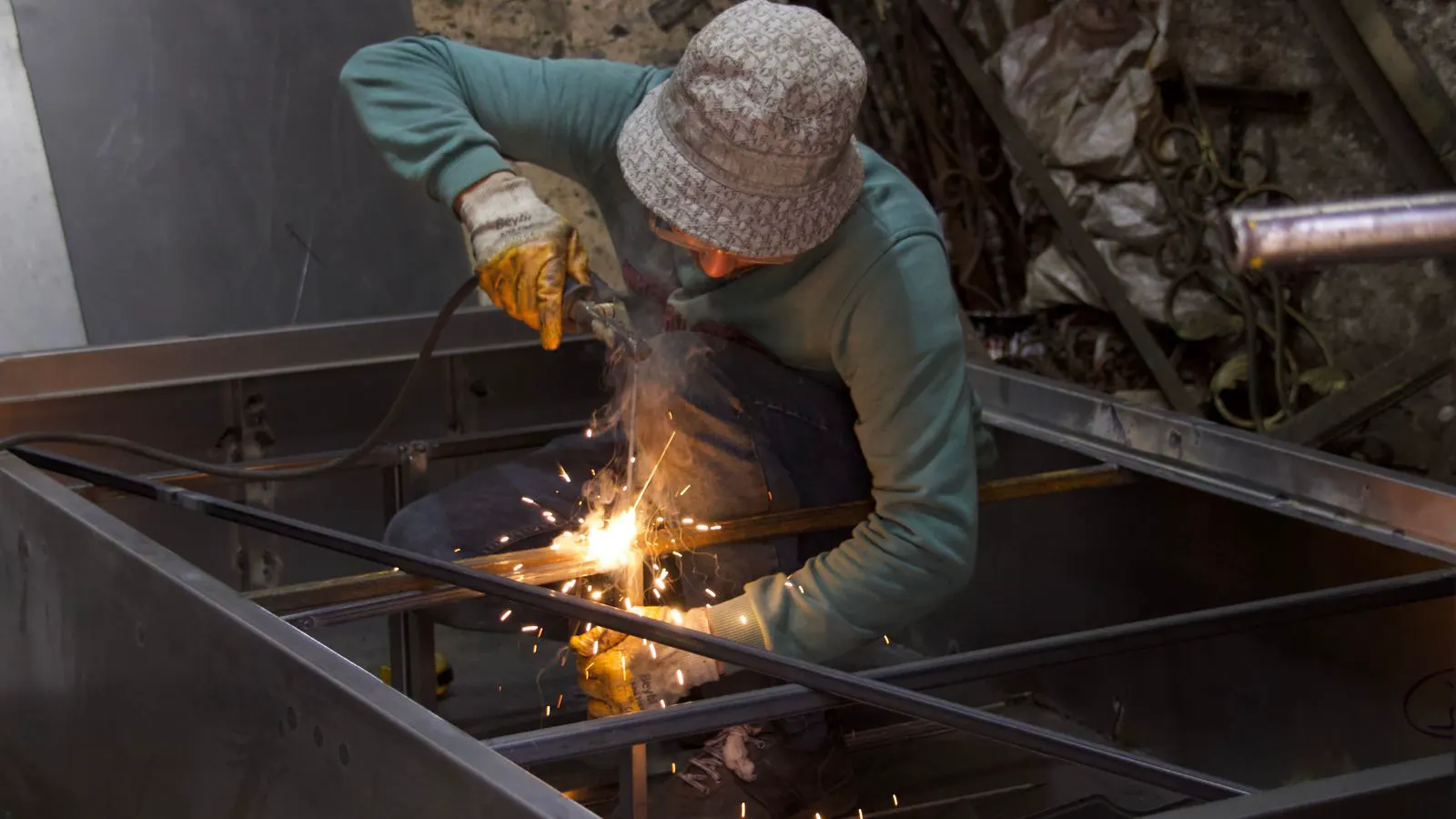
This audit checklist covers power, fixture design, safety fencing, and control verification. It helps engineers confirm that a new production line is ready for industrial welding robots before commissioning begins.
- Verify power quality and grounding before connecting the main drive unit.
- Confirm fixture repeatability and weld position accuracy with a test piece.
- Inspect safety fencing, light curtains, and e-stop wiring at every access point.
- Check the robot controller interface for correct parameter backups and version updates.
- Review the line layout for cable management and pinch points during motion.
A new line rarely fails because the robot itself is defective. It fails because the surrounding infrastructure was not verified. The checklist below audits the technical and safety prerequisites that must be met before a welding robot integration project reaches the commissioning phase.
Use this list as a pre-installation gate. Do not proceed to power-up until every item is checked and signed off by the responsible engineer.
Power and Grounding Verification
The robot drive, controller, and external equipment draw significant current. A single voltage dip can cause a parameter reset or a lost weld sequence.
- Measure the incoming voltage at the main disconnect. Confirm it sits within the manufacturer’s specified range.
- Check the neutral-to-ground voltage. If the difference exceeds the allowed limit, the controller may behave unpredictably.
- Inspect the main cable. Look for heat discoloration, loose lugs, or damaged insulation.
- Verify the grounding path. The chassis, the drive, and the external equipment must all share a common ground.
- Test the power distribution unit. Confirm the breakers are correctly rated and that the phase sequence is correct.
Red Flags:
- Voltage fluctuates by more than 5 percent during a test run.
- The neutral-to-ground voltage exceeds the manufacturer’s tolerance.
- The main disconnect is located too far from the robot for quick isolation.
- The power cable is routed near the robot arm’s swing radius.
Fixture and Workpiece Design
The robot is only as accurate as the workpiece it holds. A fixture that drifts by two millimeters will produce a weld seam that misses the target, regardless of the robot’s precision.
- Check fixture repeatability. Move a test piece through the cycle ten times. Measure the position.
- Verify weld access. Confirm the torch can reach every joint without hitting the fixture or the workpiece.
- Inspect clamping force. The clamp must hold the workpiece firmly without distorting thin sheet metal.
- Check for heat distortion. Run a test weld and measure the part after it cools.
- Confirm the workpiece is grounded. A poor ground connection will cause arcing and poor penetration.
Red Flags:
- The fixture has loose pins or worn bushings.
- The workpiece shifts during the weld cycle.
- The clamp mechanism is operated by a pneumatic cylinder without a pressure gauge.
- The fixture material is too thin and warps under heat.
Safety Fencing and Interlocks
A robotic welding cell is a high-energy environment. The safety system is the last line of defense between the operator and the moving arm.
- Verify the safety fence height and coverage. It must enclose the entire operating area.
- Test the light curtains or safety mats. Block the beam or press the mat. The robot must stop within the specified time.
- Check the emergency stop buttons. There should be at least one at each access point.
- Inspect the interlock switches. Opening a door must immediately stop the robot and cut the torch power.
- Confirm the safety PLC logic. The stop command must be verified by a second channel.
Red Flags:
- The light curtain is aimed at the ceiling instead of the floor.
- The emergency stop button is located behind the fence.
- The interlock switch is wired in parallel instead of series.
- The fence is not bolted to the floor and can be moved by hand.
Controller and Parameter Backup
The robot controller contains the program, the offsets, and the safety parameters. If this unit fails, the line stops.
- Confirm the controller software version matches the robot firmware.
- Back up all parameters to an external drive.
- Check the battery backup. A dead battery can erase the program in a few minutes.
- Verify the I/O mapping. Confirm that every external signal is assigned to the correct pin.
- Test the communication link. Check the connection to the PLC, the HMI, and the network.
Red Flags:
- The battery backup is older than three years.
- The I/O map does not match the wiring diagram.
- The communication link drops randomly during the test cycle.
- The software version is outdated and not supported by the current firmware.
Cable Management and Pinch Points
A cable that rubs against a fixture will eventually fail. A cable that is too long will tangle and cause a trip.
- Route all cables in a dedicated tray or conduit.
- Keep cables away from the robot arm’s swing radius.
- Check for pinch points. Ensure no cable is trapped between a fixture and a wall.
- Verify cable slack. There should be enough loop to allow movement without tension.
- Inspect the torch cable. It must be rated for the current and voltage of the welder.
Red Flags:
- The cable is tied with zip ties instead of cable ties.
- The cable runs across a walkway.
- The torch cable is twisted or kinked.
- There is no strain relief at the connection points.
Commissioning and Test Run
The final step is a controlled test run. Do not run at full speed. Do not run with unshielded work.
- Run the program in single-step mode. Verify each move.
- Check the torch height. Adjust the offset if the arc length is inconsistent.
- Inspect the weld bead. Look for porosity, spatter, or incomplete fusion.
- Measure the weld position. Compare it to the target.
- Log the results. Record any anomalies for the next iteration.
Red Flags:
- The arc is unstable or jumps.
- The weld bead is uneven or misses the target.
- The robot moves slowly or stalls during a move.
- The weld position shifts after the first cycle.
Documentation and Handover
A successful integration is not just about the robot working. It is about the team knowing how to run it.
- Review the operation manual. Ensure every operator has read it.
- Check the maintenance schedule. Confirm the filters, batteries, and cables are on the list.
- Verify the as-built drawings. They must match the installed equipment.
- Confirm the spare parts list. Ensure critical items are in stock.
- Sign off on the handover. All parties must agree that the system is ready for production.
Red Flags:
- The manual is missing or incomplete.
- The as-built drawings do not match the installation.
- The spare parts list is empty.
- The handover is verbal only and not documented.
This audit checklist is a starting point. Adjust it for your specific application. A line that welds thin sheet metal has different needs than a line that welds thick plate. Use this list to find the gaps before they become expensive problems.
Frequently asked questions
How long should a welding robot integration project take?
A simple single-station cell may take two to four weeks. A multi-station line with custom fixtures can take three to six months. The timeline depends on the complexity of the workpiece and the fixture design.
What is the most common mistake during integration?
Poor fixture design. If the workpiece is not held correctly, the robot cannot compensate. Always verify fixture repeatability before running the robot at speed.
Do I need a safety consultant for the installation?
Yes. A qualified safety consultant should review the fencing, interlocks, and emergency stop logic. They can identify gaps that the installation team might miss.
How do I know if the power supply is good enough?
Measure the voltage and current during a test run. If the voltage drops by more than 5 percent or the neutral-to-ground voltage is high, the power supply needs attention.
Can I use the same checklist for different robot brands?
Yes, the core principles are the same. However, check the specific manufacturer's requirements for battery backups, software versions, and safety standards.