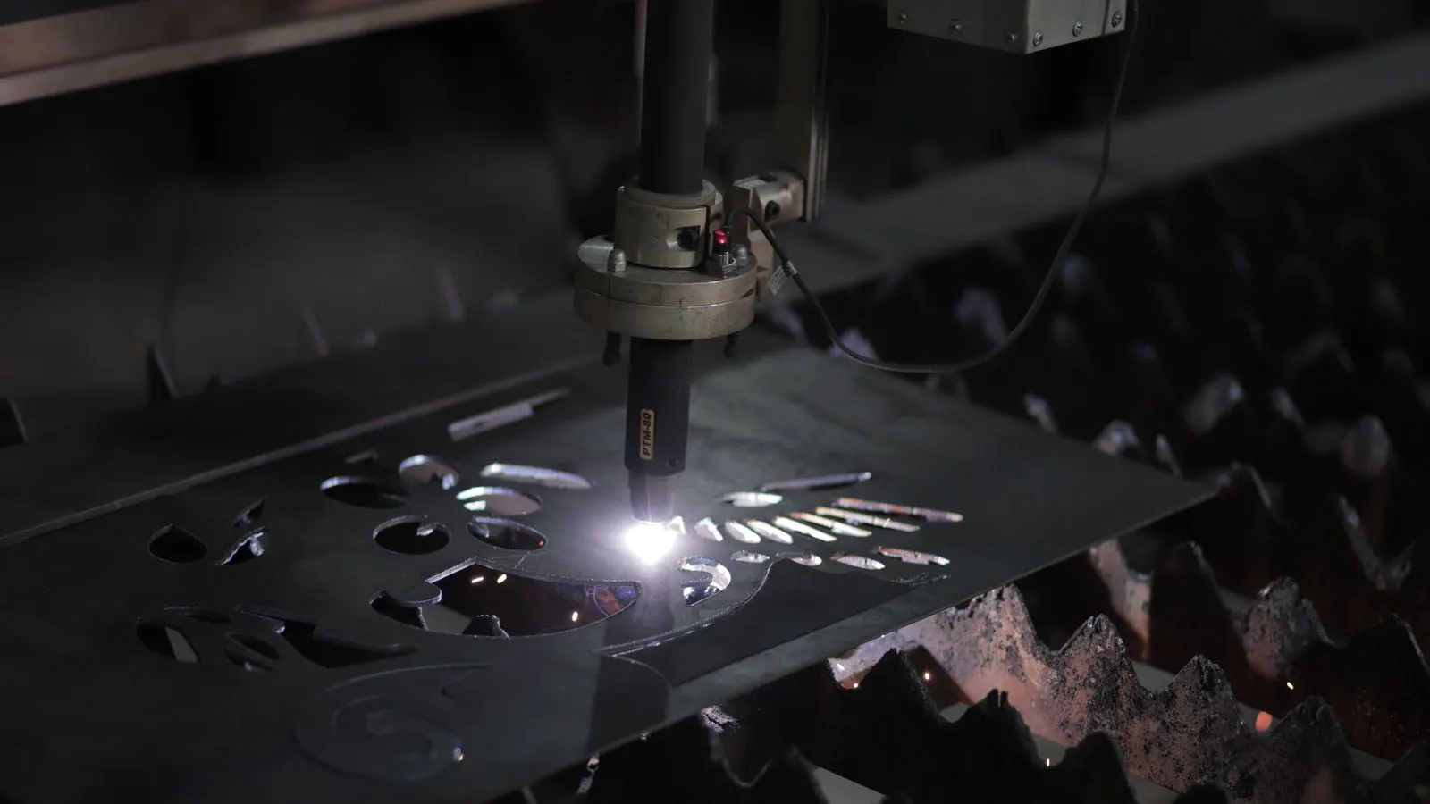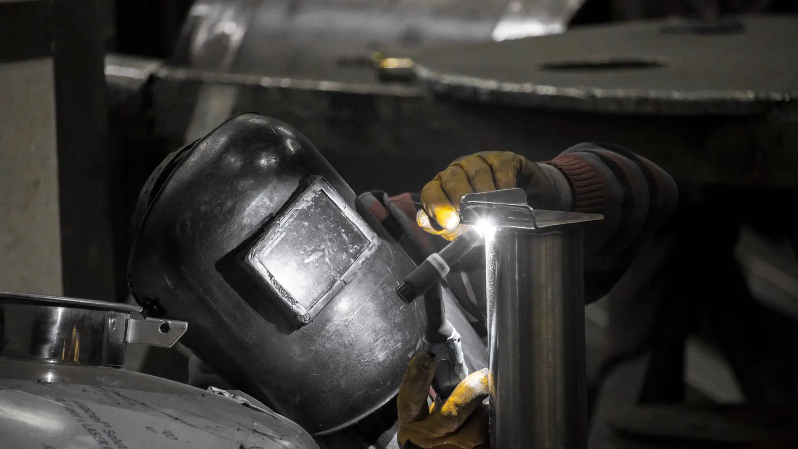
Integrating TIG and plasma stations requires coordinated power, gas, and workflow design. This guide covers practical steps to build a multi-material line that reduces changeover time, keeps operator focus high, and supports consistent quality across dissimilar materials.
- Separate TIG and plasma work zones to manage heat, fume, and power draw safely.
- Use shared gas and power infrastructure where possible, but keep control circuits independent.
- Standardize fixtures and clamping so parts move between processes without rework.
- Track each station's settings in a simple log to support repeatable multi-material results.
- Verify the full cycle with a test part before releasing production work.
Why Mixed-Material Lines Fail in Small Workshops
Many shops combine TIG and plasma equipment because one process handles fit-up and the other handles the final joint. The problem usually appears after the first week. Operators spend too long moving parts between stations. Gas lines get kinked. Power distribution overloads a circuit. The line stops because the setup was built for one process and patched for the other.
A working mixed-material line treats both processes as a single workflow. The goal is to move a part from cut to weld to finish without repositioning it more than necessary. This requires planning the station layout, electrical service, gas delivery, and operator controls before the first cut is made.
The following steps assume a shop that already owns or is purchasing TIG and plasma equipment for recurring multi-material work. The steps apply to stainless, aluminum, mild steel, and thin-to-medium plate jobs.
Prerequisites: Confirm Power, Gas, and Space
Before you move equipment, verify the physical and electrical conditions of the area.
-
Measure the available floor space. You need enough room for the part to travel between the plasma table or stand and the TIG table or fixture. A minimum of one to two meters between the two work points is typical for medium parts. More space is needed for larger sheets.
-
Check the electrical service. TIG power sources and plasma cutters both draw significant current. Confirm that the supply can handle the simultaneous load without tripping breakers. If the two stations share a circuit, the breaker may trip when both are active. Separate circuits are the standard solution.
-
Confirm gas supply. Plasma typically uses compressed air or oxygen, depending on the machine and material. TIG uses argon or a helium-argon mix. Plan where the regulators, hoses, and cylinders will sit. Keep the cylinder area ventilated and away from direct heat.
-
Identify the primary materials. Knowing whether most work is mild steel, stainless, or aluminum changes your fixture choice and gas mix. Aluminum TIG work needs more shielding gas flow and cleaner fixtures than mild steel. Stainless needs a clean environment to avoid contamination.
If any of these prerequisites are not met, the line will feel unstable from day one. Fix the infrastructure first. The equipment will perform better when the environment is set correctly.
Step 1: Define the Part Flow and Work Zones
Map the part from raw stock to finished joint. Mark where the plasma cut happens and where the TIG weld takes place.
Place the plasma station where the cut makes sense. For thin plate, a cutting table with a fume extraction system is ideal. For thicker material, a plasma stand with a portable table may be easier. The TIG station should be positioned so the operator can clamp the cut part without lifting it more than once.
Reason: A defined part flow reduces handling time and prevents parts from sitting in uncontrolled areas where they can be dented, contaminated, or misaligned.
Step 2: Standardize Fixtures and Clamping
Use the same clamping method for both processes where the geometry allows. If the part is a bracket, a pipe flange, or a thin sheet frame, design a fixture that holds the cut edges in the same position as the weld joint.
For multi-material work, use soft jaws or copper backing plates for aluminum. For stainless, use clean, dedicated clamps that have not touched rust or carbon steel. A simple fixture that holds the part by two or three points is usually enough for light TIG work.
Reason: Consistent clamping means the operator does not have to reposition the part between plasma and TIG. The joint stays in the same orientation, which improves weld quality and speeds up setup.
Step 3: Separate Power and Control Circuits
Run the TIG and plasma equipment on separate power circuits. If they must share a panel, install dedicated breakers for each and label them clearly.
Do not plug the plasma cutter into the same circuit as the TIG power source if the shop also runs a compressor, fume extractor, or welding lights on that circuit. The combined load can cause voltage drop, which changes arc stability and torch behavior.
Reason: Independent power reduces the chance of one machine interfering with the other. Voltage drop during plasma cutting can cause the TIG arc to drift or extinguish if the circuit is overloaded.
Step 4: Plan Gas and Fume Management
Run gas lines from a central manifold to each station. For plasma, use a high-pressure air or oxygen line with an appropriate regulator. For TIG, use a low-pressure argon or helium-argon line with a flow meter.
Install fume extraction at both stations. Plasma cutting produces more particulate and fume than TIG. A local extraction arm over the plasma table is more effective than a room-wide extractor for small shops.
Reason: Proper gas delivery keeps shielding consistent. Proper fume extraction protects operator health and keeps the TIG work area clean, which reduces porosity and discoloration.
Step 5: Set Up the Operator Controls
Give the operator a single, clear view of both stations. Place the TIG power source on a cart or bench at a comfortable height. Keep the plasma control panel within arm’s reach of the cutting station.
Label the gas regulators. Mark the TIG gas line with a color tag. Mark the plasma gas line with a different color. Add a small checklist card at each station that lists the typical settings for the most common materials.
Reason: A clear control layout reduces the chance of the operator selecting the wrong gas or the wrong power source. In a multi-material line, mistakes are more likely when settings are not visible and obvious.
Step 6: Create a Changeover Protocol
Write a short protocol for moving a part from plasma to TIG. The protocol should include:
- Inspect the cut edge for dross and undercut.
- Grind the edge if required for the TIG joint.
- Clean the joint area with a dedicated brush or solvent.
- Clamp the part into the TIG fixture.
- Confirm gas flow and shielding coverage before striking the arc.
Reason: A changeover protocol makes the transition repeatable. Without it, each operator handles the part differently, and the line produces inconsistent joints.
Step 7: Run a Test Cycle
Before releasing production work, run one part through the full cycle. Cut it with plasma. Move it to TIG. Weld the joint. Inspect the weld for porosity, spatter, and penetration.
Check the power draw during plasma cutting. Watch the TIG arc stability during a short weld. Verify that the gas flow meters are at the correct settings. Record the results.
Reason: A test cycle catches layout problems, gas issues, and power problems before they affect a batch of work. It also gives the operator a baseline to compare against.
Common Mistakes in Mixed-Material Setup
Sharing a single gas line. Running argon and compressed air on the same hose or manifold is a common error. The pressures are very different. A single regulator cannot handle both. Use separate lines.
Ignoring fume direction. If the fume from the plasma cut drifts toward the TIG station, the TIG operator will work in a contaminated area. Position the plasma station so the fume moves away from the TIG work zone.
Using the same fixture for all materials. A fixture that works for mild steel may not hold an aluminum part safely. Use material-specific clamps or backing plates.
Skipping the test cycle. Many shops skip the test part because they are behind schedule. This usually costs more time than it saves. A failed test cycle is cheaper than a rejected batch.
Overloading the electrical panel. Adding a second plasma cutter or a TIG machine to a panel that already runs a compressor, lights, and a fume extractor is a recipe for tripped breakers. Check the load before adding equipment.
Quick Reference: Typical Settings by Material
The table below shows general settings for common multi-material jobs. Actual values depend on part thickness, joint design, and machine rating. Use the table as a starting point, not a final setting.
| Material | Plasma Gas | TIG Gas | Typical TIG Current Range | Notes |
|---|---|---|---|---|
| Mild Steel | Compressed air or oxygen | Argon | 80 to 250 A | Grind dross before welding |
| Stainless Steel | Compressed air | Argon | 60 to 200 A | Use clean fixtures and low spatter settings |
| Aluminum | Compressed air or oxygen | Argon or helium-argon | 100 to 300 A | Use AC TIG and clean joint area |
| Thin Sheet | Compressed air | Argon | 40 to 120 A | Use low amperage and short pulses |
Final Verification Step
After the line is set up, perform a final check before the first production run.
- Walk the part path from raw stock to finished weld. Confirm the part can move without being lifted more than once.
- Turn on the plasma cutter and confirm the arc starts cleanly at the lowest and highest amperage you will use.
- Turn on the TIG power source and confirm the arc is stable at the lowest and highest amperage you will use.
- Check the gas flow meters and confirm the shielding gas is not leaking.
- Run one full test part and inspect the weld.
If the test part passes, the line is ready. If it fails, identify the cause before moving to production. A short delay to fix a gas leak or a power issue is far better than a day of rejected work.
When to Reconsider the Layout
If the line feels slow after the first month, review the layout. The most common cause is that the part is being moved more than necessary. If the plasma cut and the TIG weld are more than two meters apart, consider moving the stations closer or adding a small conveyor or lift.
If the operator is spending more than two minutes on changeover, review the fixtures. A better clamp or a dedicated backing plate can cut that time in half.
If power trips or gas pressure drops during long runs, review the electrical and gas supply. The fix is usually a larger breaker or a higher-flow regulator, not a new machine.
A well-configured TIG and plasma line is not about having the most powerful equipment. It is about removing the friction between processes. When the part flows smoothly, the operator focuses on quality, not logistics.
Frequently asked questions
Can I use the same gas line for TIG and plasma?
No. TIG uses low-pressure inert gas, while plasma uses high-pressure air or oxygen. They require separate regulators and lines.
How much space do I need between TIG and plasma stations?
One to two meters is typical for medium parts. More space is needed for larger sheets or when using overhead fume extraction.
Do I need a separate circuit for each machine?
Yes. Running TIG and plasma on the same circuit can cause voltage drop or tripped breakers, especially when both are active.
What is the most common mistake in a mixed-material line?
Sharing fixtures or gas lines between materials. This causes contamination, poor shielding, and inconsistent weld quality.
How do I know if the setup is ready for production?
Run a full test cycle with a representative part. Check the weld quality, power draw, and gas flow before releasing work.